
Balancing Strength: Steel Beam Design for Bending and Shear
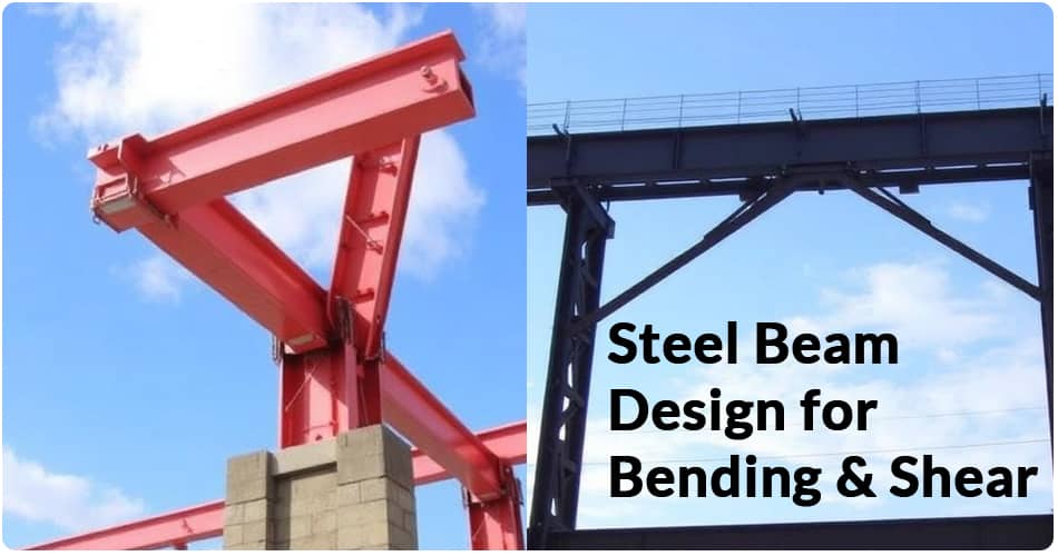
Steel beams are among the most widely used structural members in modern construction because they provide high strength, excellent ductility, efficient load-carrying capacity, and predictable structural performance. In the design of a steel beam, two of the most important structural actions that must be considered are bending moment and shear force. A beam that is adequately designed for one action but neglected for the other may not perform safely under real loading conditions.
We approach steel beam design by considering the complete structural behavior of the member. Bending resistance, shear resistance, deflection, lateral stability, local buckling, connection behavior, and load combinations must work together to produce a safe and economical design.
Understanding Bending in Steel Beams
When a steel beam carries transverse loads, it develops internal bending moments. Bending causes one region of the cross-section to experience compression while another region experiences tension. The beam must have sufficient bending strength to resist the maximum factored bending moment without excessive yielding, instability, or failure.
For a simplified elastic calculation, bending stress can be expressed as:
σ = M / Z
where:
- σ = bending stress
- M = bending moment
- Z = section modulus
The section modulus is therefore an important property when selecting a steel beam. A larger section modulus generally provides greater resistance to bending.
In practical structural design, however, we do not rely only on elastic stress calculations. We also consider the plastic moment capacity, lateral-torsional buckling, compactness of the section, local buckling, and the applicable design code.
Understanding Shear Force in Steel Beams
Shear force is another fundamental action acting on a steel beam. It is generally greatest near supports, concentrated loads, and locations where the loading changes abruptly.
The web of an I-section or H-section steel beam normally carries most of the shear force, while the flanges contribute significantly to bending resistance.
A simplified average shear stress can be expressed as:
τ = V / A
where:
- τ = average shear stress
- V = shear force
- A = relevant shear area
For detailed steel beam design, shear capacity is influenced by the web thickness, web depth, shear buckling, stiffeners, section geometry, material strength, and support conditions.
Why Both Bending and Shear Must Be Checked
A common mistake in preliminary structural design is to focus primarily on bending because bending moments often govern the selection of the beam section. However, shear cannot be ignored, particularly for short and heavily loaded beams.
A long-span beam carrying relatively distributed loads may be governed primarily by bending or deflection. In contrast, a short-span beam carrying heavy concentrated loads can develop very high shear forces.
We therefore evaluate the beam for both:
- Bending strength
- Shear strength
- Combined effects where applicable
- Deflection and serviceability
- Lateral stability
- Local and global buckling
This approach creates a more reliable and balanced structural design.
Steel Beam Design for Bending
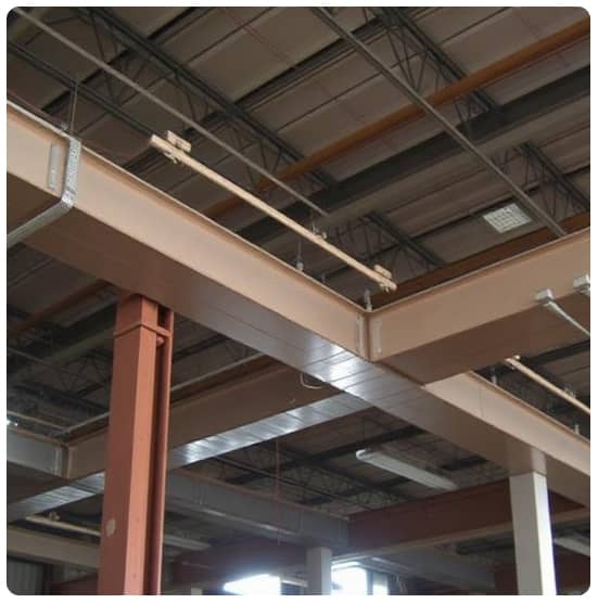
The first major stage in many beam designs is determining the maximum bending moment.
For a simply supported beam carrying a uniformly distributed load, the maximum bending moment is:
Mmax = wL2 / 8
where:
- w = uniformly distributed load
- L = span length
For a central point load on a simply supported beam:
Mmax = PL / 4
where P is the applied point load.
These equations are useful for basic beam analysis, but real structures may involve continuous spans, eccentric loading, multiple point loads, partial loading, support moments, dynamic effects, and complex load combinations.
After determining the design bending moment, we select a suitable steel section and verify that its design bending resistance exceeds the required demand.
Section Selection for Bending Resistance
Steel beam selection is strongly influenced by the required section modulus and plastic modulus. Common structural sections include:
- I-beams
- H-beams
- Universal Beams
- Universal Columns used in appropriate applications
- Wide-flange sections
- Built-up plate girders
- RHS and other hollow sections for specialized applications
For conventional building floors and roof structures, I-shaped sections are particularly efficient because the material is concentrated away from the neutral axis. This arrangement provides a high second moment of area and section modulus without requiring excessive steel weight.
Lateral-Torsional Buckling
A steel beam can have adequate theoretical bending strength but still experience failure due to lateral-torsional buckling.
This phenomenon occurs when the compression flange moves laterally and the beam simultaneously twists. The risk increases when the compression flange is unrestrained over a long length.
We therefore examine:
- Unbraced length
- Compression flange restraint
- Beam span
- Cross-sectional geometry
- Steel grade
- Moment distribution
- Lateral restraint provided by floor systems
A beam connected to a properly designed floor system may have substantially better lateral stability than an isolated beam with a completely unrestrained compression flange.
Steel Beam Design for Shear
After evaluating bending, we determine the maximum shear force.
For a simply supported beam with a uniformly distributed load, the maximum support reaction and shear force are generally:
Vmax = wL / 2
For a central point load:
Vmax = P / 2
These basic equations provide an initial understanding of beam shear. More complicated loading arrangements require appropriate structural analysis.
The beam web is then checked for sufficient shear resistance. If the web is slender, shear buckling may become important and additional measures such as stiffeners may be required.
Web Buckling and Shear Stability
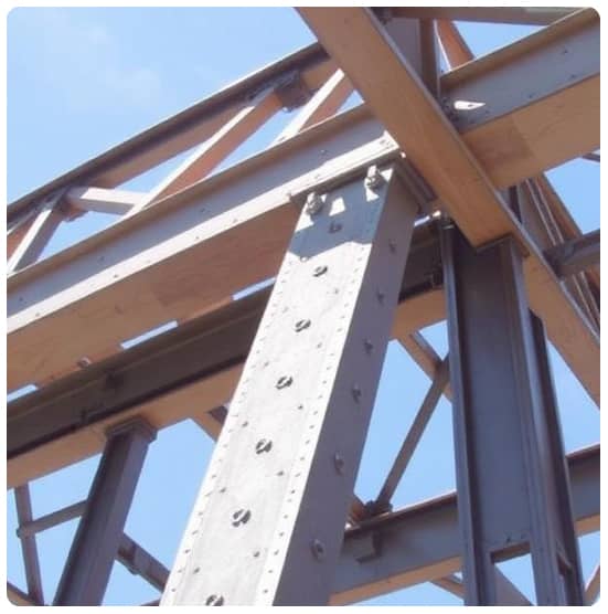
The web of a steel beam is particularly important for shear behavior. A thin web can buckle before the material reaches its full theoretical shear strength.
We therefore consider the web slenderness ratio, support conditions, load introduction points, and stiffening requirements.
Potential failure mechanisms include:
- Web shear yielding
- Web shear buckling
- Web crippling
- Web bearing failure
- Local buckling near concentrated loads
Stiffeners may be installed where high concentrated forces are introduced into the beam or where the web requires additional stability.
Interaction Between Bending and Shear
Bending and shear do not always act independently. In regions where both actions are significant, the combined stress state can influence structural capacity.
For many ordinary beams, the bending and shear checks can be performed independently when the design provisions permit it. However, high shear combined with high bending, particularly near supports or concentrated loads, may require an interaction check.
We should therefore avoid assuming that satisfying one strength requirement automatically guarantees overall beam adequacy.
Load Combinations in Steel Beam Design
Steel beams must be designed for the loads they are expected to experience throughout their service life.
Typical loads include:
- Dead loads
- Live loads
- Roof loads
- Wind loads
- Snow loads where applicable
- Equipment loads
- Partition loads
- Impact or dynamic loads
- Seismic effects where required
The relevant structural design standard determines the appropriate load factors and load combinations.
Using unfactored service loads for strength design or incorrectly combining loads can lead to an unsafe or uneconomical design. We therefore establish the governing load combinations before determining the design bending moment and shear force.
Deflection and Serviceability Requirements
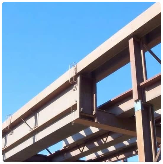
Strength is only one part of successful steel beam design. A beam can possess adequate ultimate capacity but still perform poorly if it deflects excessively.
Excessive deflection can cause:
- Cracking of finishes
- Damage to partitions
- Uneven floors
- Ponding on roofs
- Door and window problems
- Poor appearance
- Vibrations and occupant discomfort
We therefore check both strength and serviceability.
The allowable deflection depends on the structural application, span, finishes, occupancy, and applicable design standards. In many practical projects, the required beam size is controlled by deflection rather than bending strength.
Choosing the Most Efficient Steel Beam
The strongest beam is not necessarily the best beam. Efficient design seeks an appropriate balance between:
Strength + Stability + Serviceability + Constructability + Cost
A very heavy section may have excessive capacity but increase material costs, transportation requirements, lifting demands, and connection complexity.
An undersized section may reduce initial steel tonnage but create problems with deflection, vibration, connections, or structural safety.
We therefore select a beam that provides sufficient capacity while remaining economical, practical, and compatible with the overall structural system.
Connection Design and Its Relationship to Beam Strength
The beam itself is only one component of the load path. Loads must transfer safely through the beam connections into columns, walls, foundations, and ultimately the ground.
Connections may include:
- Bolted connections
- Welded connections
- End-plate connections
- Fin-plate connections
- Moment-resisting connections
- Shear connections
The connection must be capable of transferring the required forces and moments without premature failure.
A beam with excellent bending and shear capacity can still be unsafe if its connection is inadequately designed. Consequently, beam design and connection design should be treated as parts of the same structural load path.
Support Conditions and Their Effect on Beam Design
Support conditions significantly influence bending moments and shear forces.
A simply supported beam generally develops positive bending moments between supports. A continuous beam can develop both positive and negative moments. A cantilever beam experiences maximum bending moment at its fixed support.
Changing the support arrangement can therefore change:
- Maximum bending moment
- Shear distribution
- Deflection
- Required steel section
- Connection requirements
- Reinforcement or supporting member requirements
Accurate structural modeling is essential when the actual support conditions are more complicated than an idealized textbook arrangement.
Practical Steel Beam Design Workflow
A structured workflow helps reduce design errors. We generally proceed through the following stages:
1. Establish the Structural Geometry
Determine the span, support arrangement, beam spacing, floor or roof system, and framing configuration.
2. Determine Design Loads
Calculate dead, live, environmental, equipment, and other applicable loads.
3. Apply Appropriate Load Combinations
Determine the governing combinations for ultimate and serviceability conditions.
4. Analyze the Beam
Calculate the required bending moments, shear forces, reactions, and deflections.
5. Select a Preliminary Steel Section
Choose a suitable section based on section properties, span, loading, and practical considerations.
6. Check Bending Capacity
Verify that the beam's design bending resistance exceeds the required bending demand.
7. Check Shear Capacity
Verify the web and overall section for the governing shear force.
8. Check Stability
Evaluate lateral-torsional buckling, local buckling, web stability, and other applicable instability modes.
9. Check Deflection
Verify serviceability limits under appropriate service-load combinations.
10. Design Connections
Ensure that the connection safely transfers the required reactions, shear forces, axial forces, and moments.
11. Review Constructability
Confirm that the selected section can be fabricated, transported, lifted, connected, and installed efficiently.
Common Steel Beam Design Mistakes
Several mistakes can compromise otherwise careful structural work.
Ignoring lateral stability can result in a beam failing through lateral-torsional buckling before reaching its nominal bending capacity.
Checking bending but ignoring shear can be dangerous for short-span or heavily loaded beams.
Ignoring deflection can produce serviceability problems even when strength requirements are satisfied.
Using incorrect load combinations can lead to either unsafe or unnecessarily conservative designs.
Ignoring connection behavior can interrupt the intended structural load path.
Selecting a section without considering availability can increase fabrication and procurement difficulties.
A complete design should address these issues before the final section is approved.
Role of Structural Design Standards
Steel beam design should always follow the structural design code applicable to the project location and building type. Depending on the jurisdiction and project requirements, designers may work with standards such as AISC, Eurocode, IS 800, BS standards, or other nationally adopted structural codes.
The selected standard establishes requirements for:
- Material properties
- Section classification
- Bending resistance
- Shear resistance
- Buckling
- Load combinations
- Deflection
- Connections
- Safety factors
- Design methodologies
The numerical equations and resistance factors can differ between standards, so calculations should not mix provisions from different codes without appropriate engineering justification.
Modern Tools for Steel Beam Design
Modern structural engineering increasingly uses specialized analysis and design software to improve productivity and reduce calculation errors.
Structural analysis platforms can model complex frames and automatically generate:
- Bending moment diagrams
- Shear force diagrams
- Support reactions
- Deflection results
- Load combinations
- Member forces
Steel design software can then perform code-based checks for bending, shear, axial forces, buckling, interaction, and serviceability.
However, software output must always be reviewed by a qualified structural professional. A software model is only as reliable as its geometry, assumptions, boundary conditions, loads, material properties, and design settings.
Conclusion: Achieving a Balanced Steel Beam Design
Effective steel beam design is about more than simply selecting a section that can withstand a calculated bending moment. We must consider the complete structural behavior of the beam, including bending, shear, stability, deflection, connections, load combinations, and constructability.
Bending strength determines whether the beam can safely resist flexural demand, while shear strength ensures that the web and section can transfer vertical forces without yielding or buckling. At the same time, lateral-torsional buckling and local instability can reduce the practical capacity of a beam, making stability checks essential.
The most effective approach is therefore a balanced design strategy. By accurately establishing loads, analyzing the structural system, selecting an efficient steel section, checking bending and shear resistance, verifying serviceability, and designing reliable connections, we can achieve steel structures that are safe, economical, durable, and efficient.
For real construction projects, final member sizing and structural calculations should be completed and verified in accordance with the applicable design standard and by an appropriately qualified structural engineer.